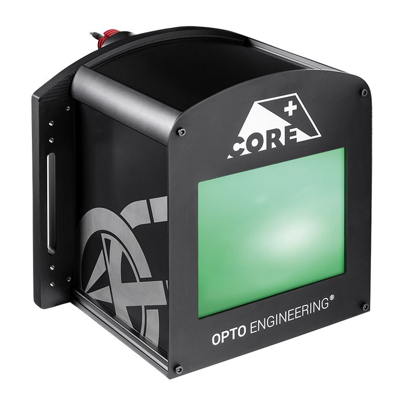
LTCLHP CORE PLUS series
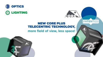
Compact telecentric illuminators for large FOV systems


Key advantages
- Large illumination area in a super compact form factor
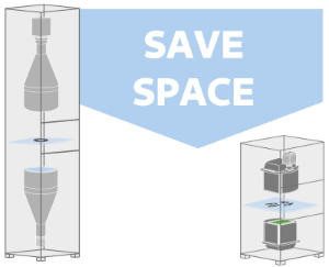
LTCLHP CORE PLUS are up to 40% shorter than other telecentric lights on the market. - Reduce the size of your vision system
The working distance of LTCLHP CORE PLUS telecentric illuminators has been optimized to reduce the overall system’s footprint. - Boost your measurement system’s performance
LTCLHP CORE PLUS illuminators may be used in place of flat backlights to improve your system’s performance. - Smart integration
LTCLHP CORE PLUS illuminators integrate a mounting flange for easy integration without additional clamps. - System compactness is a competitive advantage
A smaller vision system or measurement machine is preferred by the industry.
LTCLHP CORE PLUS telecentric illuminators are designed to illuminate large areas in a reduced space. They are up to 40% shorter than other telecentric lights on the market.
The length and working distance of a telecentric lens strongly impact the size of a vision system. Their working distance range has been optimized to make a measurement system as compact as possible, allowing to reduce the overall system’s dimensions by up to up to half.
The super compact form factor allows you to easily integrate CORE PLUS collimated illumination where classic telecentric lights don’t fit instead of common diffuse backlights, thus improving your system’s performance.
LTCLHP CORE PLUS lights have been designed for smart integration. They feature a built-in mounting flange so no additional clamps are required.
Advantages
Save more
• Lower manufacturing cost due to less material employed
• Cost of mounting is reduced as no addictional clamps are needed
• Less space required for storage and use
• Lower shipment expenses due to smaller size
• Lower transportation risks
Sell more
• Compactness brings a competitive advantage
Notes
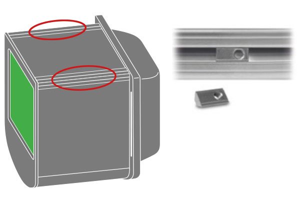
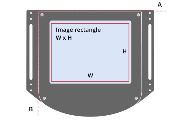
- Beam shape is not circular. See Tech Info for minimun beam dimensions.
- Opto Engineering® recommends green light for high precision measurement applications.
- Tolerance ± 10%.
- At max forward current. Tolerance is ± 0.06V on forward voltage measurements.
- In continuous mode (not pulsed).
- At pulse width <= 10 ms and duty cycle <= 10%. Built-in electronics board must be bypassed (see tech info).
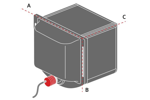
- Maximum dimension of the clamping flange.
- Nominal value, with no spacers in place.
Specifications
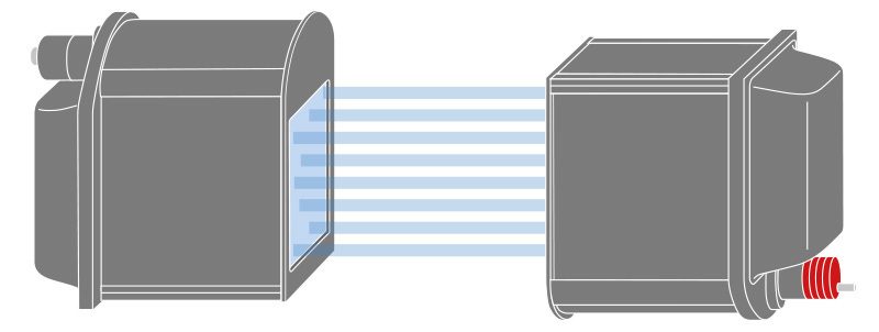
Setup instructions 1
To build a telecentric measurement setup it’s necessary to position a LTCLHP CORE telecentric illuminator upside down with respect to the TC CORE PLUS telecentric lens.
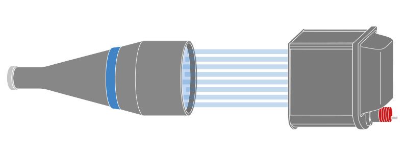
Setup instructions 2
LTCLHP CORE PLUS telecentric illuminator is also a perfect solution when coupled with classic telecentric lenses (e.g. TC series).
Application cases